3. Introduction
OpenPOWER Cluster Genesis (OPCG) enables greatly simplified configuration of clusters of bare metal OpenPOWER servers running Linux. It leverages widely used open source tools such as Cobbler, Ansible and Python. Because it relies solely on industry standard protocols such as IPMI and PXE boot, hybrid clusters of OpenPOWER and x86 nodes can readily be supported. Currently OPCG supports Ethernet networking with separate data and management networks. OPCG can configure simple flat networks for typical HPC environments or more advanced networks with VLANS and bridges for OpenStack environments. OPCG also configures the switches in the cluster. Currently Mellanox SX1410 is supported for the data network and the Lenovo G8052 is supported for the management network.
3.1. Overview
OPCG is designed to be easy to use. If you are implementing one of the supported architectures with supported hardware, OPCG eliminates the need for custom scripts or programming. It does this via a configuration file (config.yml) which drives the cluster configuration. The configuration file is a yaml text file which the user edits. Example YAML files are included. The configuration process is driven from a “deployer” node which does not need to remain in the cluster when finished. The process is as follows;
- Rack and cable the hardware.
- Initialize hardware.
- initialize switches with static ip address, userid and password.
- insure that all cluster compute nodes are set to obtain a DHCP address on their BMC ports.
- Install the OpenPOWER Cluster Genesis software on the deployer node.
- Edit an existing config.yml file.
- Run the OPCG software
- Power on the cluster compute nodes.
When finished, OPCG generates a YAML formatted inventory file which can be read by operational management software and used to seed configuration files needed for installing a solution software stack.
3.1.1. Hardware and Architecture Overview
The OpenPOWER Cluster Genesis software supports clusters of servers interconnected with Ethernet. The servers must support IPMI and PXE boot. Currently single racks with single or redundant data switches (with MLAG) are supported. Multiple racks can be interconnected with traditional two tier access-aggregation networking. In the future we plan to support two tier leaf-spine networks with L3 interconnect capable of supporting VXLAN.
3.1.2. Networking
The data network is implemented using the Mellanox SX1410 10 Gb switch. Currently OPCG supports up to four ethernet interfaces. These interfaces can be bonded in pairs with support for LAG or MLAG.
Templates are used to define multiple network configurations in the config.yml file. These can be physical ports, bonded ports, Linux bridges or vLANS. Physical ports can be renamed to ease installation of additional software stack elements.
Management and/or Data switches can be set to “passive” mode to allow deployment without supplying login credentials to the switch management interfaces. This mode requires the user to manually write switch MAC address tables to file and to configure the management and/or data switch in accordance with the defined networks. The client networks will still be configured by Cluster Genesis.
3.1.3. Compute Nodes
OPCG supports clusters of heterogeneous compute nodes. Users can define any number of node types by creating templates in a config file. Node templates can include any network templates defined in the network templates section. The combination of node templates and network templates allows great flexibility in building heterogeneous clusters with nodes dedicated to specific purposes.
3.1.4. Supported Hardware
Compute Nodes
OpenPOWER Compute Nodes;
- S812LC
- S822LC
- Tyan servers derived from the above 2 nodes are generally supported.
- SuperMicro OpenPOWER servers
x86 Compute Nodes;
- Lenovo x3550
- Lenovo x3650
Switches
For information on adding additional switch support using Genesis’ switch class API, (see Developer Guide)
Data Switches;
- Mellanox SX1410
- Mellanox SX1710
Support for Lenovo G8264 is planned
Management Switches;
- Lenovo G8052
4. Prerequisite hardware setup
4.1. Hardware initialization
- Insure the cluster is cabled according to build instructions and that a list of all switch port to compute node connections is available and verified. Note that every node to be deployed, must have a BMC and PXE connection to a management switch. (see the example cluster in Appendix-D)
- Cable the deployer node to the cluster management network. It is required that the deployer node be connected directly to the management switch. For large cluster deployments, a 10 Gb connection is recommended. The deployer node must also have access to the public internet (or site) network for accessing software and operating system image files. If the cluster management network does not have external access, an alternate connection with external access must be provided such as the cluster data network, or wireless etc.
- Insure that the BMC ports of all cluster nodes are configured to obtain an IP address via DHCP.
- If this is a first time OS install, insure that all PXE ports are also configured to obtain an ip address via DHCP. On OpenPOWER servers, this is typically done using the Petitboot menus.
- Acquire any needed public and or site network addresses
- Insure you have a config.yml file to drive the cluster configuration. If necessary, edit / create the config.yml file (see section 4 Creating the config.yml File)
Configuring the Cluster Switches
If your switches are a supported model, Genesis can fully configure them. (See Supported Hardware for a list of supported switches.) Even if your switch models are not supported by Cluster Genesis, you can still use Cluster Genesis to deploy and configure your cluster compute nodes. Genesis supports a ‘passive’ switch mode which enables this. (See : Preparing for Passive Mode)
Initial configuration of data switch(es)
For out of box installation, it is usually easiest to configure the switch using a serial connection. See the switch installation guide. Using the Mellanox configuration wizard;
assign hostname
set DHCP to no for management interfaces
set zeroconf on mgmt0 interface: to no
do not enable ipv6 on management interfaces
assign static ip address. This must match the address specified in the config.yml file (keyname: ipaddr-data-switch:) and be in a different subnet than your cluster management subnet used for BMC and PXE communication.*
assign netmask. This must match the netmask of the subnet the deployer will use to access the management port of the switch.
default gateway
Primary DNS server
Domain name
Set Enable ipv6 to no
admin password. This must match the password specified in the config.yml file (keyword: password-data-switch:). Note that all data switches in the cluster must have the same userid and password.
disable spanning tree (typical industry standard commands; enable, configure terminal, no spanning-tree or for Lenovo switches spanning-tree mode disable)
enable SSH login. (ssh server enable)
If this switch has been used previously, delete any existing vlans which match those specified in the network template section of the config.yml file. This insures that only those nodes specified in the config file have access to the cluster. (for a brand new switch this step can be ignored)
login to the switch:
enable
configure terminal
show vlan
note those vlans that include the ports of the nodes to be included in the new cluster and remove those vlans or remove those ports from existing vlans:
no vlan nSave config. In switch config mode:
configuration writeIf using redundant data switches with MLAG, Leave the interswitch peer links (IPL) links disconnected until Cluster Genesis completes. (This avoids loops)
Initial configuration of management switch(es)
For out of box installation, it is usually necessary to configure the switch using a serial connection. See the switch installation guide. For additional info on Lenovo G8052 specific commands, see Appendix G. and the Lenovo RackSwitch G8052 Installation guide)
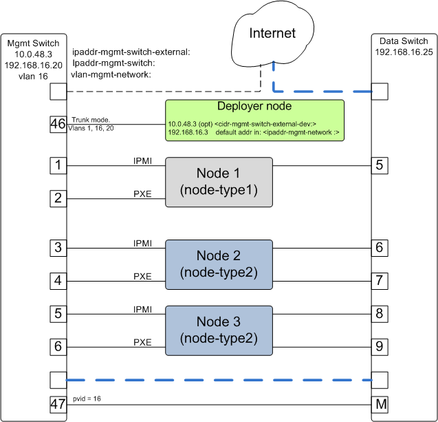
In order for Cluster Genesis to access and configure the switches in your cluster it is necessary to configure management access on all switches and provide management access information in the config.yml file. The diagram below shows the intitial switch setup and the corresponding config file entries;

Initial switch setup
In this example, the management switch has an in-band management interface. The initial setup requires an ‘externally’ accessible address on an in-band interface of all management switches. (‘Externally’ accessible is used here to mean external to the cluster. ie on the customers’ management intranet) Cluster genesis uses this address along with the provided userid and password credentials to access the management switch initially. Cluster genesis will create a vlan isolated management network for accessing the management interfaces of the switches in your cluster. A new management interface is created on the management switch in the vlan indicated by the config.yml file. The ‘externally’ accessible inerface is left unchanged and is available for external monitoring or other purposes. In addition, a vlan is created on the management switches for isolating access to the pxe and BMC interfaces of all node in the cluster.
The following entries in the config.yml file relate to initial switch setup;
cidr-mgmt-switch-external-dev: 10.0.48.3/20 # example address
Address on the deployer node for access to the customers external management network. Used by Cluster Genesis for initial management switch access. It is optional to configure this address on an interface on the deployer. If it is not configured, Genesis will configure it temporarily and then remove it when it has finished configuring the management network.
- ipaddr-mgmt-switch-external:
rack1: 10.0.48.20 # example address
Address of the management switch on the customers external management network. Used by Cluster Genesis for initial management switch access.
port-mgmt-network: 46
Specifies the port on the management switch that the deployer is connected to.
ipaddr-mgmt-network: 192.168.16.0/24
Defines the private network that Genesis creates for access to the management interfaces of switches in the cluster. Although the user is free to change this, it is usually not necessary as Genesis will vlan isolate this network so that it will not conflict with existing networks in the customer environment.
- ipaddr-data-switch:
rack1: 192.168.16.25
Address on the data switch in the private network that genesis creates. Currently the user needs to set up this address on the data switches before running Cluster Genesis. In the future, Genesis will automatically create this address. This address must be within the subnet defined by the ipaddr-mgmt-network: value. Optionally, the customer may also set up a management interface in his external subnet for monitoring or other management purposes.
- port-mgmt-data-network:
rack1: - 45
Ports on the management switch which connect to management ports on the data switches.
Genesis setup of the switch management network
Management switch setup commands. (for G8052)
Enable configuration of the management switch:
enable
configure terminal
Enable IP interface mode for the management interface:
RS G8052(config)# interface ip 1assign a static ip address, netmask and gateway address to the management interface. This must match the address specified in the config.yml file (keyname: ipaddr-mgmt-switch-external:) and be in a different subnet than your cluster management subnet:
RS G8052(config-ip-if)# ip address 10.0.48.20 (example IP address)
RS G8052(config-ip-if)# ip netmask 255.255.240.0
RS G8052(config-ip-if)# vlan 1       (User selectable, usually default vlan 1 is used)
RS G8052(config-ip-if)# enable
RS G8052(config-ip-if)# exit
Optionally configure a default gateway and enable the gateway:
RS G8052(config)# ip gateway 1 address 10.0.48.1  (example ip address)
RS G8052(config)# ip gateway 1 enable
admin password. This must match the password specified in the config.yml file (keyword: password-mgmt-switch:). Note that all management switches in the cluster must have the same userid and password. The following command is interactive:
access user administrator-passworddisable spanning tree (for Lenovo switches enable, configure terminal, spanning-tree mode disable):
spanning-tree mode disableenable secure https and SSH login:
ssh enable
ssh generate-host-key
access https enable
Save the config (For Lenovo switches, enter config mode For additional information, consult vendor documentation):
copy running-config startup-config
This completes normal Genesis initial configuration.
Preparing for Passive Mode
In passive mode, Genesis configures the cluster compute nodes without requiring any management communication with the cluster switches. This facilitates the use of Genesis even when the switch hardare is not supported or in cases where the end user does not allow 3rd party access to their switches. When running Genesis in passive mode, the user is responsible for configuring the cluster switches. The user must also provide the Cluster Genesis software with MAC address tables collected from the cluster switches during the Genesis process. For passive mode, the cluster management switch must be fully programmed before beginning cluster genesis, while the data switch should be configured after Genesis runs.
Configuring the management switch(es)
- The port connected to the deployer node must be put in trunk mode with allowed vlans vlan-mgmt-network and vlan-mgmt-client-network added. (see Appendix - B The System Configuration File for a description of these config file keys)
- The ports on the management switch which connect to the management ports of cluster data switches must be in access mode and have their PVID (Native VLAN) value set to vlan-mgmt-network
- The ports on the management switch which connect to cluster node BMC ports or PXE ports must be in access mode and have their PVID (Native VLAN) set to vlan-mgmt-client-network
Configuring the data switch(es)
Configuration of the data switches is dependent on the user requirements. The user / installer is responsible for all configuration. Generally, configuration of the data switches should occur after Cluster Genesis completes. In particular, note that it is not usually possible to aquire complete MAC address information once vPC (AKA MLAG or VLAG) has been configured on the data switches.
4.2. Setting up the Deployer Node
Requirements; It is recommended that the deployer node have at least one available core of a XEON class processor, 16 GB of memory free and 64 GB available disk space. For larger cluster deployments, additional cores, memory and disk space are recommended. A 4 core XEON class processor with 32 GB memory and 320 GB disk space is generally adequate for installations up to several racks.
The deployer node requires internet access. This can be achieved through the interface used for connection to the management switch (assuming the management switch has a connection to the internet) or through another interface.
Operating Sytem and Package setup of the Deployer Node
- Deployer OS Requirements:
- Ubuntu
- Release 14.04LTS or 16.04LTS
- SSH login enabled
- sudo privileges
- RHEL
- Release 7.2
- Extra Packages for Enterprise Linux (EPEL) repository enabled (https://fedoraproject.org/wiki/EPEL)
- SSH login enabled
- sudo privileges
Optionally, assign a static, public ip address to the BMC port to allow external control of the deployer node.
- login into the deployer and install the vim, vlan, bridge-utils and fping packages
Ubuntu:
$ sudo apt-get update
$ sudo apt-get install vim vlan bridge-utils fping
RHEL:
$ sudo yum install vim vlan bridge-utils fping
Network Configuration of the Deployer Node
Note: The deployer port connected to the management switch must be defined in /etc/network/interfaces (Ubuntu) or the ifcfg-eth# file (RedHat).
ie:
auto eth0      # example device name
iface eth0 inet manual
Genesis sets up a vlan and subnet for it’s access to the switches in the cluster. It is recommended that the deployer be provided with a direct connection to the management switch to simplify the overall setup. If this is not possible, the end user must insure that tagged vlan packets can be communicated between the deployer and the switches in the cluster.
The following keys are used to provide initial access to the switches in the cluster and must be assigned in the config.yml file
- ipaddr-mgmt-switch
- ipaddr-data-switch
- vlan-mgmt-network
- ipaddr-mgmt-switch-external
- cidr-mgmt-switch-external-dev
- port-mgmt-data-network
For a detailed description of these keys, see Appendix - B The System Configuration File and Genesis setup of the switch management network.
There are two options for configuring network setup on the deployer. With the first option, Genesis will attempt to discover the deployer port connected to the management switch and configure a temporary address on it for accessing the management switches. For the second option, the user can optionally assign the label-mgmt-switch-external-dev key in the config file to skip the auto discovery. In this case, the user must configure the specified port so that it can access the management switches on the ‘external’ management network.